

 Language
  English
 中文简体
中文简体 Español
 عربى
عربىHome / News / Industry News / 2/0 Aluminum Wire Ampacity: NEC Ratings, Derating Factors and Application Tips
Industry News

Content
Ask three people on a jobsite how many amps 2/0 aluminum wire can carry and you will often get three different answers. The question is not vague; the number simply changes with the conditions. A 2/0 AWG aluminum conductor with a 75°C rating is good for 135 A in a typical raceway, yet that figure can fall to around 95 A once ambient temperature and conductor count are applied, or climb well above 150 A in free air with a 90°C insulation system.
Because so much depends on context, the most reliable approach is to start from the published table and then apply the corrections your installation actually faces. This guide does exactly that, beginning with the base ampacity of 2/0 aluminum wire and finishing with the connection details that keep a feeder running cool for decades.
2/0 AWG is spoken as "two aught" and written as 00 AWG. The conductor has a cross-sectional area of about 133,100 circular mils, roughly 67.4 mm², with a nominal diameter of 9.27 mm. It sits between 1/0 AWG and 3/0 AWG in the American Wire Gauge series and is one of the most common sizes for low-voltage feeders, service conductors, and distribution circuits where a moderate current has to travel a fair distance.
One clarification saves a great deal of confusion: 2/0 AWG is not the same as 2 AWG. A 2 AWG aluminum conductor has about 33.6 mm² of cross-section and is rated 90 A at 75°C, which is why questions about pushing 125 amps through "2 AWG aluminum" usually end with a recommendation to move up in size. Going from 2 AWG to 2/0 AWG roughly doubles the metal area and adds around fifty percent to the ampacity.
Aluminum conductors at this size appear in several forms. Bare strands are used in overhead lines as AAC, AAAC, and ACSR constructions, while insulated versions appear as XHHW, THWN, USE, and low-voltage XLPE or PVC power cable. Copper-clad aluminum, which has a thin copper skin over an aluminum core, is listed alongside aluminum in most ampacity tables.
The table below gives the base ampacity of a 2/0 AWG aluminum conductor, with copper values included for comparison. These numbers assume not more than three current-carrying conductors in a raceway or cable at a 30°C ambient temperature.
| Temperature rating | 2/0 aluminum ampacity | Common insulation types | 2/0 copper ampacity |
|---|---|---|---|
| 60°C | 115 A | TW, UF | 145 A |
| 75°C | 135 A | RHW, THWN, XHHW, USE | 175 A |
| 90°C | 150 A | THHN, THWN-2, XHHW-2, USE-2 | 195 A |
Two caveats travel with these figures. First, ampacity tables are revised from time to time, and the 2023 edition of the National Electrical Code adjusted selected values, so the edition adopted in your jurisdiction governs. Second, projects outside North America may work from IEC or other regional standards, where conductor sizes are expressed in square millimetres rather than AWG.
Ampacity is the maximum current a conductor can carry continuously without exceeding its rated temperature. Heat is the limiting factor, so a conductor with 90°C insulation can run hotter and therefore carry more current than the same conductor with 60°C insulation.
The column you can actually use, however, is set by the weakest link in the circuit. Code rules require ampacity to be based on the lowest temperature rating of any termination, conductor, or device in the circuit. Most breakers, lugs, and panelboards are rated for 75°C conductors, so for a 2/0 aluminum feeder the practical number is usually 135 A even when the cable itself is an XHHW-2 or THHN product rated 90°C.
The higher figure is not wasted. You may begin derating calculations from the 90°C column, provided the final result does not exceed the ampacity permitted by the terminations. In practice, 150 A is a starting point for the arithmetic, not a value you can load to.
Overcurrent protection follows similar logic. Under the next-size-up allowance, a 2/0 aluminum conductor with a 135 A ampacity can be protected by a 150 A device when the calculated load does not exceed 135 A, but that allowance carries conditions and belongs in the design documentation.
Real installations rarely match the baseline conditions of three conductors, a 30°C ambient, and a single unbundled layer. Four corrections account for most of the difference:
For a deeper look at how conductor stranding and installation method feed into these same calculations, see our guide to NEC ampacity ratings and derating factors.
Suppose a 2/0 aluminum XHHW-2 feeder in a raceway supplies a distribution panel, with four current-carrying conductors and a design ambient temperature of 40°C. Working through the corrections step by step gives a realistic answer rather than a table answer.
This is where solid manufacturer data helps, because conductor dimensions, insulation thickness, and temperature ratings all feed the same calculation.
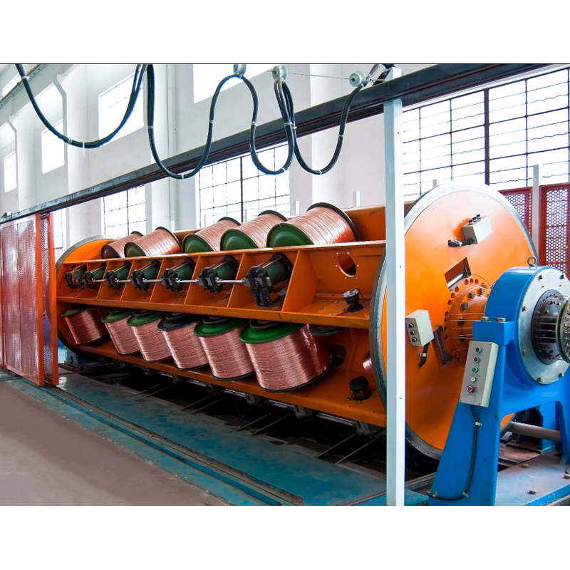 XLPE/PVC Insulated Power Cable for Rated Voltage 0.6/1kVThe product is manufactured according to the standards of GB12706 and GB12666, or IEC, BS, DIN, ICEA, and JIS upon request.View Product →
Our low-voltage XLPE and PVC power cable range covers the 0.6/1 kV feeders in which 2/0 aluminum is most often specified, and our engineers are happy to run the derating numbers with you.
At 2/0 AWG the comparison is direct: 135 A against 175 A at 75°C, so aluminum delivers roughly three quarters of the copper ampacity in the same physical size. Aluminum conducts about 61 percent of what copper does, but because heat dissipation depends on surface area as well as resistance, the ampacity gap is narrower than the conductivity gap. As a rule of thumb, an aluminum conductor is upsized by one trade size to match a copper ampacity.
The advantages are weight and cost. Aluminum is roughly a third the density of copper, which matters on long pulls, elevated trays, and pole-top work, and it costs considerably less per ampere delivered. The trade-off is connection sensitivity: aluminum oxidizes quickly and creeps under sustained pressure, so terminations must be listed for the metal, prepared carefully, and tightened to the torque printed on the lug.
Copper-clad aluminum sits between the two. Its ampacity is normally taken from the aluminum column, while its surface behaves more like copper for corrosion and connection purposes, which is why it remains popular in smaller branch circuits.
At 135 A, a 2/0 aluminum conductor covers a broad and practical band of applications:
Where a run leaves the ground and climbs a pole, bare aluminum conductors take over from insulated cable, and the construction changes from insulation-limited to tension-limited.
 AAAC、AAC & ACSRAluminum alloy stranded wire, aluminum stranded wire, and steel-core aluminum stranded wire are commonly used high-efficiency conductor materials in overhead transmiss...View Product →
Our AAAC, AAC, and ACSR bare conductor range is built for exactly those overhead circuits, with the stranding and mechanical properties specified for the span.
Free air changes the ampacity picture considerably. A conductor exposed to wind and cooler ambient air sheds heat far more effectively than a cable buried in conduit, and published free-air values can exceed raceway values by more than twenty percent for the same size. Once ampacity stops being the binding constraint, the limiting factors shift to sag, tension, wind loading, and the temperature rating of the insulation and hardware.
Aerial insulated cable for 1 kV through 35 kV is often the most practical choice for overhead distribution where trees, buildings, or public access make bare conductors a poor option. Sunlight resistance, tracking resistance, and correct tension for the span matter as much as the ampacity table itself.
 Aerial Insulated Cable For Rated Voltage1kV、10kV、20kV、35kVStandard The products shall comply with the standards GB 12527-2008 and GB14049-2008 and Q/320282GAD023 Applications The products fit for transmitting line and distrib...View Product →
Our aerial insulated cable line covers the 1 kV, 10 kV, 20 kV, and 35 kV levels for exactly this kind of mixed urban and rural route.
Aluminum has a reputation problem that is mostly a workmanship problem. A few disciplined habits prevent the great majority of failures:
After the first heating and cooling cycles, a quick re-check of torque and a thermographic scan of the terminations will catch almost anything that slipped through during installation.
Aluminum conductors have been a standard part of power distribution for decades, and 2/0 AWG remains one of the most useful sizes in the range. Treat 135 A at 75°C as the starting point, apply the corrections your installation demands, and give the terminations the attention they deserve, and a 2/0 aluminum feeder will perform reliably for the life of the system.
That is the approach we take every day. Established in 1988, our company manufactures low-voltage through high-voltage cables, including 0.6/1 kV XLPE and PVC power cables, bare and aerial conductors, control and equipment cables, and specialty products for fire-resistant, high-temperature, and renewable energy applications. Our engineering team routinely reviews ampacity, derating, and installation conditions with customers before a single drum is scheduled. If you are sizing a new feeder or replacing an existing run, send us the load details, ambient conditions, and route information, and we will confirm the conductor size and cable construction that fits the job.
Your email address will not be published. Required field are marked*

Choosing our wires and cables means choosing safety, reliability, and professionalism.


 +86-17826659260
 +86-0510-87203139
 West of Huanzheng Road, Guanlin Town, Yixing City, Wuxi City, Jiangsu Province, China