

 Language
 English
 中文简体
 Español
 عربى
Home / News / Industry News / 69 kV Transmission Line Guide: Cable Design, Structures, and Project Planning
Industry News

Content
A 69 kV transmission line is one of those network assets that rarely gets attention until something goes wrong. It sits above the distribution circuits that serve homes and businesses, but below the bulk transmission corridors that move power across regions. At 69,000 volts line-to-line, it is not the highest voltage on the system, yet it carries real power and leaves little room for casual assumptions. The useful questions are practical: overhead or underground, which conductor, what insulation and shield, how will it be installed, and can it be maintained for decades?
In North America, 69 kV is a familiar subtransmission voltage. Utilities often use it to connect bulk supply points to distribution substations, or to tie substations together within a city or industrial area. In other regions, 66 kV or 70 kV may occupy a similar role, so the first step is to confirm the actual system nominal voltage and insulation coordination—not simply copy a 69 kV drawing from another project.
Terminology varies. Some owners classify 69 kV as transmission; others call it subtransmission because it feeds the distribution system. The label matters less than the design basis. A 69 kV line must satisfy clearances, insulation levels, fault duty, grounding, and right-of-way requirements that are specific to the owner and the local code. The voltage class tells you where the line sits in the network. It does not tell you the conductor size, structure type, cable shield arrangement, or installation method.
Most 69 kV lines are overhead. That is not a sentimental preference; it is usually the most practical way to cross long distances with acceptable cost and repair access. Underground cable becomes attractive for short sections where right-of-way is tight, visual impact matters, or a substation tie must pass under a road, river, or dense development. The decision should compare lifecycle cost, outage risk, permitting, and maintainability—not only the first invoice.
| Aspect | Overhead 69 kV line | Underground 69 kV cable |
|---|---|---|
| Typical use | Long rural and suburban routes, substation ties | Short urban crossings, congested corridors, sensitive sites |
| Right of way | Wide, visible, and subject to clearance rules | Narrow trench or duct bank, but permanent easements still matter |
| Fault repair | Often faster; damaged conductor or insulator can be replaced | Requires locating, excavation, splicing, and longer outages |
| Cost profile | Usually lower for long distances | Higher material and installation cost; can be justified in constrained areas |
| Best fit | Open routes with maintainable access | Short, difficult, or visually sensitive segments |
The table is a starting point, not a cost estimate. A 69 kV underground section can be perfectly rational when it avoids a long permitting fight or protects a critical crossing. It can also become an expensive obligation if the route, thermal backfill, and joint locations are not planned together.
Overhead 69 kV lines are built with bare conductors and air insulation. Common conductor choices include AAC, AAAC, and ACSR, with the final selection driven by ampacity, sag, tension, corrosion environment, and fault current. AAC offers good conductivity; AAAC brings strength through an aluminum alloy; ACSR uses a steel core for higher tension and longer spans. The best conductor is the one that satisfies the electrical and mechanical duty for the actual route.
Structures may be wood poles, steel poles, concrete poles, or lattice towers. A 69 kV line often uses suspension and strain insulator strings, guy wires, and grounding arrangements that reflect local lightning and soil conditions. Phase spacing, clearance to ground and objects, and right-of-way width all matter. So does access: a line that cannot be inspected or worked on safely is a design problem, even if it looks neat on paper.
 AAAC, AAC and ACSR Overhead ConductorsCompare AAAC, AAC and ACSR options to align conductor selection with tower loading, sag and insulator hardware.View Product →
For projects that need bare overhead conductors, reviewing the AAAC, AAC, and ACSR options early helps the electrical and structural design move together. Conductor choice affects tower loading, sag, and the insulator hardware around it.
An underground 69 kV cable is not a scaled-up low-voltage cable. A typical XLPE-insulated power cable uses a stranded copper or aluminum conductor, an inner semiconductive screen, XLPE insulation, an outer semiconductive screen, a metallic shield or sheath, and an outer sheath. The semiconductive layers control the electric field. The metallic layer carries fault current and excludes moisture. The oversheath protects the cable from mechanical and environmental damage.
For 69 kV service, the cable must be selected as a system: conductor size, insulation thickness, metallic sheath type, jacket material, joints, and terminations all interact. Corrugated aluminum sheath, for example, can provide a robust moisture barrier and mechanical protection for high-voltage XLPE cables, but its bonding and grounding must be designed correctly. A cable that is excellent in a factory test can still fail early if the shield circulation, pulling tension, or backfill is wrong.
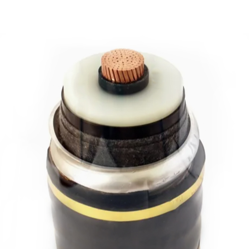 66–500 kV XLPE Power Cable SeriesReview this 66–500 kV XLPE cable range to coordinate conductor, insulation, sheath and termination choices for high-voltage routes.View Product →
Our 66–500 kV XLPE power cable range is organized around this kind of system view, so the cable construction can be matched to the route and the network rather than chosen from a single catalog line.
Ampacity is not one number printed on a datasheet. For an underground 69 kV cable, it depends on conductor resistance, insulation temperature limit, burial depth, soil thermal resistivity, duct bank arrangement, ambient temperature, grouping, and the bonding of metallic sheaths. For an overhead line, it depends on conductor type, wind, ambient temperature, solar exposure, and the permitted sag. The same 69 kV circuit can have very different ratings above and below ground.
Shielding and grounding deserve early attention. At 69 kV, the metallic shield or sheath is not optional decoration; it is part of the electrical design. Poorly planned bonding can create circulating currents, reduce ampacity, or raise sheath voltage. Joints and terminations are equally important. They are often the most exposed parts of an underground cable system, and they need clean installation conditions and proper testing.
Installation planning should cover pulling tension, sidewall pressure, bend radius, trench or duct details, thermal backfill, joint bay locations, and the space needed for terminations. For a broader comparison of voltage classes and cable selection logic, our high-voltage cable selection guide is a useful companion to a project-specific review.
When a 69 kV line is moving from concept to procurement, the most useful conversations happen before the specification is frozen. We have seen schedules improve when the owner, engineer, and supplier agree on a few basics early:
Clear answers to those questions reduce rework. They also make it easier to compare offers fairly, because cable price alone says little about the delivered system.
A 69 kV transmission line is a long-term piece of infrastructure, whether it is a familiar overhead subtransmission route or a short underground cable tie. The sound approach is neither to overcomplicate it nor to treat it as routine. Match the voltage class to the network, choose conductors and cable construction for the real route, and design the installation, shielding, and terminations as one system. That is how the line stays quiet—in the best sense—for the decades it is expected to serve.
Your email address will not be published. Required field are marked*

Choosing our wires and cables means choosing safety, reliability, and professionalism.


 +86-17826659260
 +86-0510-87203139
 West of Huanzheng Road, Guanlin Town, Yixing City, Wuxi City, Jiangsu Province, China