

 Language
 English
 中文简体
 Español
 عربى
Home / News / Industry News / 750 MCM Diameter: Conductor Size, Cable OD, and Practical Selection Guide
Industry News

Content
If you are looking for a single number for 750 MCM diameter, the honest answer is that there are two: the conductor diameter and the finished cable diameter. A solid 750 MCM conductor is about 0.866 in (22.0 mm) across. A conventional stranded 750 MCM conductor is closer to 1.0 in (25 mm). Once insulation, a metallic shield, and a jacket are added, the outside diameter can easily reach 35 mm to 55 mm or more, depending on voltage class and construction.
This guide explains where those numbers come from, how stranding changes them, and what to confirm before you order or install 750 kcmil cable.
MCM stands for thousand circular mils. The older Roman numeral M means 1,000, and CM means circular mil. So 750 MCM is the same as 750 kcmil: a conductor area of 750,000 circular mils. One circular mil is the area of a circle with a diameter of one mil, or 0.001 in.
Converted to metric area, 750 MCM is about 380 mm². That surprises people because 750 MCM sounds larger than it is. A 750 mm² metric cable is roughly 1,480 kcmil, almost double the metal area. Before you compare prices or check a duct, confirm whether the specification is in MCM/kcmil or mm².
The diameter of a round conductor follows directly from its area: d = √(4A/π). For a solid 750 MCM conductor, that gives 866 mils, or 0.866 in (22.0 mm). For a stranded conductor, the same metal area is divided among many wires, so the overall diameter is larger than the solid equivalent unless the conductor is compacted.
For planning, separate the conductor diameter from the cable outside diameter. The table below gives indicative values for common constructions.
| Construction | Typical nominal diameter | What it tells you |
|---|---|---|
| Solid round copper | 22.0 mm (0.866 in) | Theoretical minimum; stiff and rarely used at this size. |
| Compact stranded copper or aluminum | 23.5–24.5 mm (0.93–0.96 in) | Reduced voids; smaller OD for tight ducts. |
| Conventional 61-strand conductor | About 25.3 mm (1.00 in) | More flexible; overall diameter depends on stranding class. |
| 0.6/1 kV XLPE single-core cable | About 33–36 mm | Insulation and jacket add roughly 8–11 mm over the conductor. |
| 8.7/15 kV XLPE single-core cable | About 41–45 mm | Shield and thicker insulation increase the OD. |
| 18/30 kV XLPE single-core cable | About 50–55 mm | Check bend radius, cleats, and joint space early. |
Use these figures to plan, not to order. For low-voltage feeders, our 0.6/1 kV XLPE/PVC power cable range is a practical starting point for checking construction options.
 0.6/1 kV XLPE/PVC Power CableFor low-voltage feeder planning, this cable lists fire-resistant and steel-tape armored constructions with PVC or XLPE insulation options.View Product →
Stranding is the main reason two 750 MCM cables with the same metal area can have different conductor diameters. A conventional concentric stranded conductor leaves gaps between wires. A compact stranded conductor presses the wires into a tighter shape, reducing the overall diameter by several percent. Compressed stranded constructions sit between the two.
Take a 61-strand 750 kcmil conductor. Each strand is about 110.9 mils (2.82 mm) in diameter. In an uncompressed concentric lay, the overall conductor diameter is about nine strand diameters, or 25.3 mm. A compacted version of the same conductor is often closer to 24 mm. That difference looks small, but it matters in conduit fill, cable cleat size, and the radius of a bending shoe.
Stranding also changes flexibility and installation behavior. Larger strand counts generally bend more easily, while compact conductors save space. For overhead lines, AAAC, AAC, and ACSR constructions use different strand arrangements and sometimes steel cores, so the outside diameter must come from the conductor table, not from the kcmil value alone.
 AAAC, AAC and ACSR Overhead ConductorsFor overhead transmission and distribution, these aluminum, alloy, and steel-reinforced conductors offer different strength and conductivity balances across listed sizes.View Product →
At 750 MCM, the conductor is only the core. The finished cable diameter is driven by voltage class. A 0.6/1 kV cable may have a few millimetres of XLPE or PVC insulation and a simple jacket. A 6–35 kV cable adds semiconductive screens, a metallic shield, and a thicker oversheath. High-voltage cables add a metallic sheath, bedding, armor, or a moisture barrier, so the same conductor can sit inside a cable more than twice its diameter.
This is why a simple “750 MCM diameter” search can mislead. The number you need for a bend radius, duct, or cable gland is the finished cable OD from the manufacturer’s drawing, not the conductor diameter. For 6–35 kV distribution feeders, our medium-voltage XLPE range is built around these construction choices.
 Medium-Voltage XLPE Power Cable, 3.6/6–26/35 kVFor 6–35 kV distribution feeders, this XLPE cable offers copper or aluminum conductors, armoured or unarmoured constructions, and 90°C continuous operation.View Product →
Two cables can both be called 750 MCM and still have different outside diameters because standards and construction details differ. IEC, BS, UL, and ASTM designations do not use identical insulation walls, sheath thicknesses, or tolerance rules. Copper and aluminum conductors of the same circular-mil area have essentially the same nominal conductor diameter, but the cable weight and the connector selected will differ.
Insulation material also matters. XLPE allows a thinner wall than some older PVC or paper-insulated designs for the same voltage, while EPR may require a different thickness. Armor, lead sheath, radial moisture barriers, and flame-retardant jackets all add diameter. Manufacturing tolerances then add a small band around the nominal value. For replacement work, measure the old cable OD, photograph the gland and cleat, and compare the manufacturer’s drawing. A few millimetres can decide whether a cable fits an existing duct or termination.
A clear specification prevents most diameter surprises. Use this checklist:
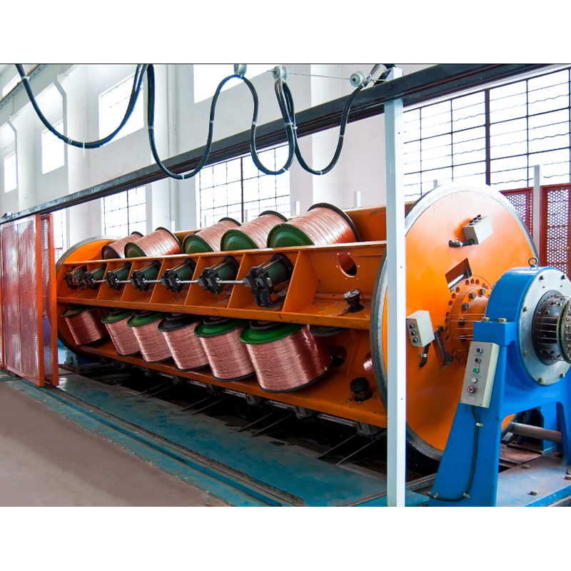
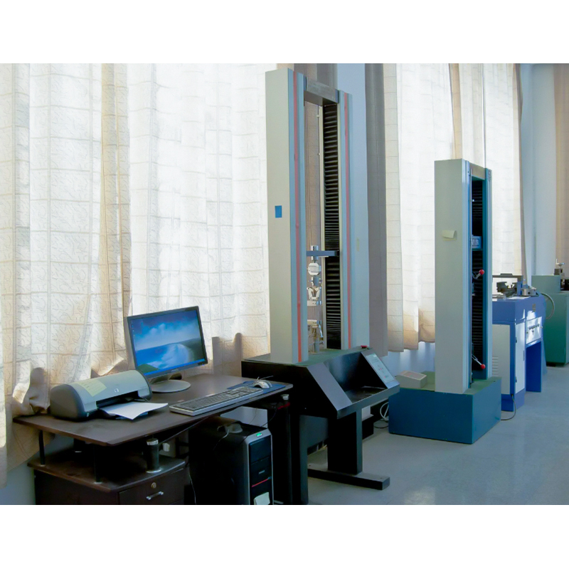
We have been manufacturing cable since 1988, and the most common late change we see is a missing installation detail. If you want to see how we control those details, visit our factory or review our quality process. A useful inquiry includes the conductor size in MCM or mm², voltage, standard, installation method, and the maximum outside diameter your duct or gland can accept.
On site, confirm the cable OD with a caliper at several points, not just the label. Check the bend radius against the manufacturer’s data and the installation standard. Confirm that lugs, ferrules, and mechanical connectors are listed for 750 kcmil, and that the die or tooling matches the conductor material and stranding. For long pulls, calculate pulling tension using the actual weight and friction, not a rule of thumb based on diameter.
Ampacity deserves the same care. Two 750 MCM cables with different insulation, installation methods, and ambient temperatures will not carry the same current. Diameter tells you whether the cable fits; it does not tell you whether the circuit is safe.
So the practical answer to “750 MCM diameter” is this: expect about 22 mm for a solid conductor, about 24–25 mm for a typical stranded conductor, and roughly 33–55 mm for a finished low- and medium-voltage cable, with high-voltage constructions larger still. Treat those as planning figures. The number that belongs on the purchase order is the nominal outside diameter and tolerance from the manufacturer’s drawing for the exact construction you are buying.
If you are comparing 750 MCM with a metric 750 mm² cable, check the units first. That single step avoids most of the confusion around size, weight, duct fill, and price.
Your email address will not be published. Required field are marked*

Choosing our wires and cables means choosing safety, reliability, and professionalism.


 +86-17826659260
 +86-0510-87203139
 West of Huanzheng Road, Guanlin Town, Yixing City, Wuxi City, Jiangsu Province, China