

 Language
  English
 中文简体
中文简体 Español
 عربى
عربىIndustry News

Industry News
High Voltage Wire & Cable Selection Guide: From 1kV to 500kV
2026-07-08Content
- 1 What is High Voltage Wire and Cable?
- 2 Key Applications of High Voltage Cables
- 3 High Voltage Cable Construction: A Deep Dive into Materials
- 4 How to Choose the Right High Voltage Cable for Your Project
- 5 High Voltage Cable Standards and Certifications
- 6 Why Choose a Full-Line Manufacturer for Your High Voltage Cable Needs?
A single fault in a high-voltage cable termination can shut down a 200 MW wind farm for days. That’s the reality of high-voltage infrastructure — the wire you specify either keeps your project online or becomes the weakest link. While the term “electric wire high voltage” gets thrown around in spec sheets, the real question is how to match the right cable to the voltage, load, and environment without overspending or compromising safety.
This guide cuts through the noise. You’ll get a clear voltage classification, see exactly how insulation and shielding affect performance, and walk away with a five-step selection method. No vague theory — only what procurement engineers, project managers, and system designers need to make informed decisions.
What is High Voltage Wire and Cable?
High-voltage (HV) wire and cable are designed to transmit electrical power at voltages above 1,000 volts AC. Anything below that threshold falls into low-voltage territory, where insulation requirements and construction are far simpler. The industry generally splits voltage levels into four buckets:
- Low Voltage: below 1 kV — used in residential, commercial, and light industrial distribution
- Medium Voltage: 1 kV to 35 kV — backbone of factory power, data centers, and wind farm collector grids
- High Voltage: 35 kV to 230 kV — long-distance transmission, substation interconnections, large industrial loads
- Extra-High Voltage: above 230 kV — bulk power transfer across regions, often 500 kV and beyond
What makes electric wire high voltage fundamentally different is its layered construction. A typical HV cable includes a metallic conductor, conductor screen, thick insulation, insulation screen, metallic shield, and outer jacket — each layer engineered to manage electric field stress, prevent partial discharge, and withstand thermal cycling. A low-voltage building wire simply has a conductor and a basic PVC jacket.
Key Applications of High Voltage Cables
High-voltage cables show up wherever large amounts of power must move reliably. The requirements, though, vary wildly by application.
- Grid transmission and distribution: Utilities use underground HV cables (69 kV and up) to connect substations in urban areas where overhead lines aren’t feasible. XLPE-insulated cables with corrugated aluminum sheaths are standard here because they combine high ampacity with a robust moisture barrier.
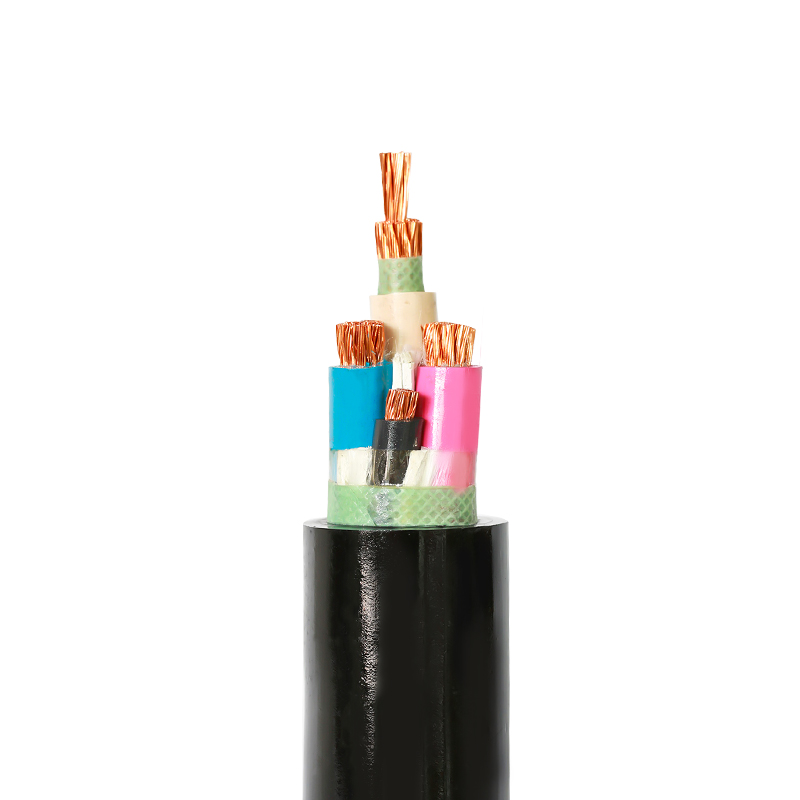
- Heavy industry: Steel mills, chemical plants, and mining operations deploy 6.6 kV to 35 kV cables to feed arc furnaces, crushers, and large motors. Tough rubber-sheathed cables often serve as flexible connections in these harsh environments. See tough rubber insulated cable rated up to 450/750V and beyond for example constructions.
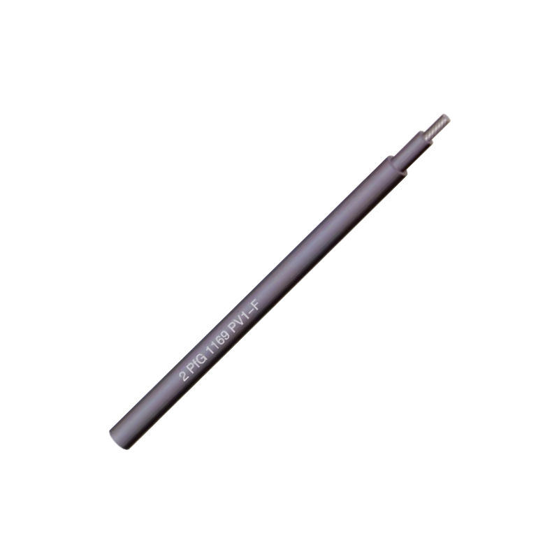
- Renewable energy: Photovoltaic arrays generate DC power at 1,500 V system voltage, pushing the boundary between low- and medium-voltage class. Specialized photovoltaic cable must resist UV, ammonia, and extreme temperature swings while maintaining low leakage current over a 25-year service life. Wind farms rely on medium-voltage cables from the turbine nacelle down to the collector substation, often subjected to continuous vibration and torsion.
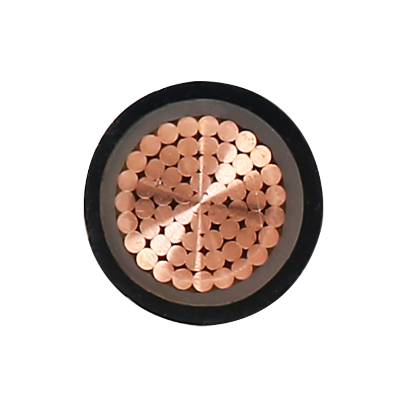
- Electric vehicle charging: The shift to 800 V vehicle architectures and ultra-fast chargers demands HV cables that are lightweight, highly flexible, and capable of carrying high currents without overheating. EV charging cables rated 450/750V integrate power conductors, signal lines, and cooling in one jacket — a far cry from traditional static infrastructure cables.
- Rail and mass transit: Subway systems and light rail networks use 15 kV to 25 kV cables for traction power, often installed in tunnels where fire performance and low smoke emission are non-negotiable.
High Voltage Cable Construction: A Deep Dive into Materials
If you strip back a high-voltage cable, you’ll find more than just copper and plastic. Every layer performs a precise electrical or mechanical function. The insulation material and the metallic shield have the biggest impact on long-term reliability and cost, so they deserve a close comparison.
Insulation Materials: XLPE vs. EPR
Cross-linked polyethylene (XLPE) dominates the HV cable market above 6 kV. It offers high dielectric strength, low dielectric losses, and a continuous operating temperature of 90°C. EPR (ethylene propylene rubber) steps in where flexibility and higher heat tolerance matter more than up-front cost.
| Property | XLPE | EPR |
|---|---|---|
| Max. continuous conductor temperature | 90°C | 90°C – 150°C (depending on compound) |
| Dielectric strength | High | Moderate to high |
| Water tree resistance | Good (with tree-retardant compounds) | Excellent |
| Flexibility | Stiff | Very flexible |
| Relative cost | Lower | Higher |
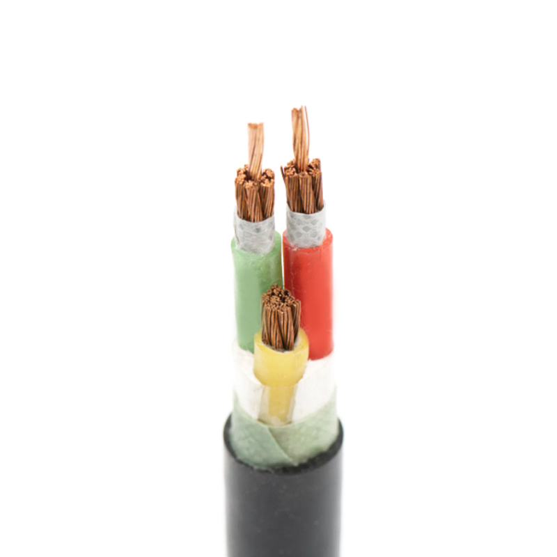
XLPE is the default choice for static installations — underground feeders, substation connections, and wind farm collector circuits. EPR becomes attractive for high-temperature resistant control cable applications or any location where the cable must flex repeatedly. If your project runs in a high-humidity environment with a known water tree risk, EPR’s inherent resistance can eliminate the need for expensive metallic moisture barriers in medium-voltage ranges.
Metallic Shield Configuration
The metallic shield serves two purposes: carrying fault current and providing a ground plane that keeps the electric field contained within the insulation. The shield type directly influences the cable’s short-circuit rating, bending radius, and installation method.
| Shield Type | Short-Circuit Rating | Moisture Barrier | Minimum Bending Radius |
|---|---|---|---|
| Copper tape | Moderate | Poor (water can wick at overlaps) | 12–15× overall diameter |
| Concentric copper wire | High | Poor | 8–12× overall diameter |
| Corrugated aluminum sheath | Very high | Excellent (fully welded, impervious) | 20–25× overall diameter |
For extra-high voltage projects — think 66 kV to 500 kV — a corrugated aluminum sheath is almost always specified. It acts as the metallic shield, radial moisture barrier, and mechanical armor in one seamless layer. Our XLPE insulation cable with corrugated aluminum sheath rated up to 500 kV is built exactly this way, designed for direct burial and subsea applications where water ingress would be catastrophic.
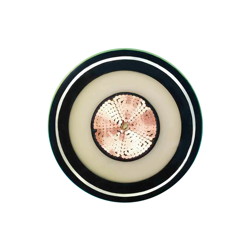
For medium-voltage indoor or cable tray installations, a copper tape shield provides adequate short-circuit performance at a lower cost and tighter bending radius. Always verify the shield’s short-circuit current rating against your system’s available fault current — an undersized shield turns a phase-to-ground fault into a cable fire.
How to Choose the Right High Voltage Cable for Your Project
Selection errors typically come from focusing on voltage alone. A 15 kV cable might meet the dielectric requirement but fail thermally if the conductor size wasn’t properly derated for the soil thermal resistivity at your site. Follow these five steps to get it right the first time.
- Determine system voltage and BIL. Note the nominal U0/U (phase-to-ground/phase-to-phase) voltage and the basic impulse insulation level. A 10 kV system with a high BIL may push you into a 15 kV voltage class cable.
- Calculate required ampacity under installation conditions. The same conductor can carry much less current when buried in dry sand than when hanging in free air. Use IEC 60287 or Neher-McGrath calculations to derate for ambient temperature, grouping, and soil thermal resistivity.
- Select insulation and jacket based on environment. Wet location? Choose tree-retardant XLPE or EPR with a sealed metallic sheath. High UV exposure? Specify a carbon-black-stabilized PE jacket or PVC with UV inhibitors. For fire-critical installations, consider flexible fireproof cable rated 6/1 kV that maintains circuit integrity during a blaze.

- Match the shield to the system’s short-circuit requirements. Calculate the maximum phase-to-ground fault current and duration. Confirm that the chosen shield cross-section and material can handle that energy without melting or deforming the insulation.
- Identify any special mechanical or chemical demands. Does the cable route pass through an area with known rodent or termite activity? Specify a nylon or brass-tape overlay. Will it run inside a 2-inch conduit with multiple bends? Switch to a compact-stranded conductor and a reduced-wire shield for flexibility.
When these variables are documented, the cable specification practically writes itself — and you avoid the expensive “value engineering” that often backfires during commissioning.
High Voltage Cable Standards and Certifications
A cable design that hasn’t been type-tested to international standards is a gamble. European projects typically reference IEC standards, while North American ones lean on UL and ICEA, and China’s domestic market requires GB compliance. Knowing which standard applies to your jurisdiction keeps the cable off the rejection dock.
- IEC 60502-2: covers power cables with extruded insulation for rated voltages from 6 kV up to 30 kV. This is the most widely referenced standard for medium-voltage XLPE and EPR cables globally.
- IEC 60840: applies to extruded insulation power cables for rated voltages above 30 kV up to 150 kV, including testing for partial discharge, bending, and heating cycles.
- IEC 62067: extends the same requirements to cables above 150 kV up to 500 kV, covering extra-high-voltage XLPE cables.
- GB/T 12706: is the Chinese national standard equivalent, with identical insulation thickness and test sequences for the 3.6/6 kV to 26/35 kV range.
- UL 1072: governs medium-voltage power cables in the U.S., focusing on conductor sizes, insulation thickness, and flame propagation tests.
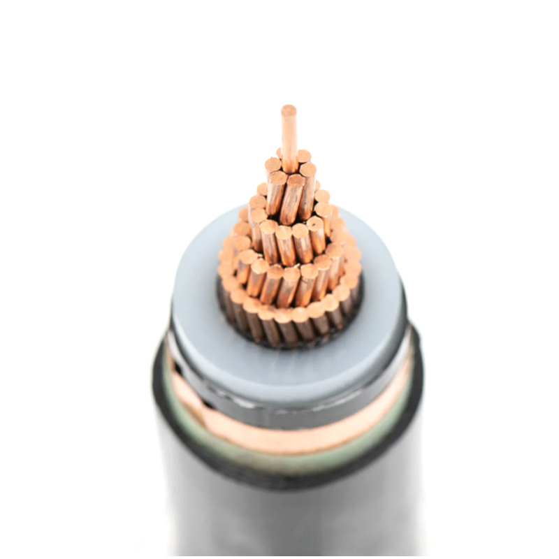
When a manufacturer holds type-test certifications for both IEC and GB series — and can supply test reports on request — project engineering teams save weeks of document review. The full product line across 3.6/6kV to 35kV XLPE power cable and higher voltage ranges adheres to these benchmarks, simplifying qualification for mixed-standard projects.
Why Choose a Full-Line Manufacturer for Your High Voltage Cable Needs?
Procurement managers often default to buying medium-voltage cable from one supplier and extra-high-voltage from another. That fragmentation adds hidden costs and risks. A single manufacturer delivering everything from 0.6/1 kV low-voltage distribution up to 500 kV transmission cable changes the equation.
- Simplified logistics and lower total cost. Consolidating cable orders across voltage levels typically cuts 15–20% from administrative and freight expenses while eliminating the finger-pointing that occurs when multiple vendors’ cable accessories don’t mate properly.
- Faster, more predictable lead times. A fully integrated domestic factory with in-house conductor drawing, insulation extrusion, and testing avoids the queue delays common when a supplier subcontracts any production step.
- Access to non-standard, project-specific designs. Need a hybrid cable with integrated fiber for distributed temperature sensing? Or a 500 kV submarine cable with dual-layer armoring? A facility with a provincial enterprise technology center and a special cable development track can engineer those without requiring an MOQ in the hundreds of kilometers.
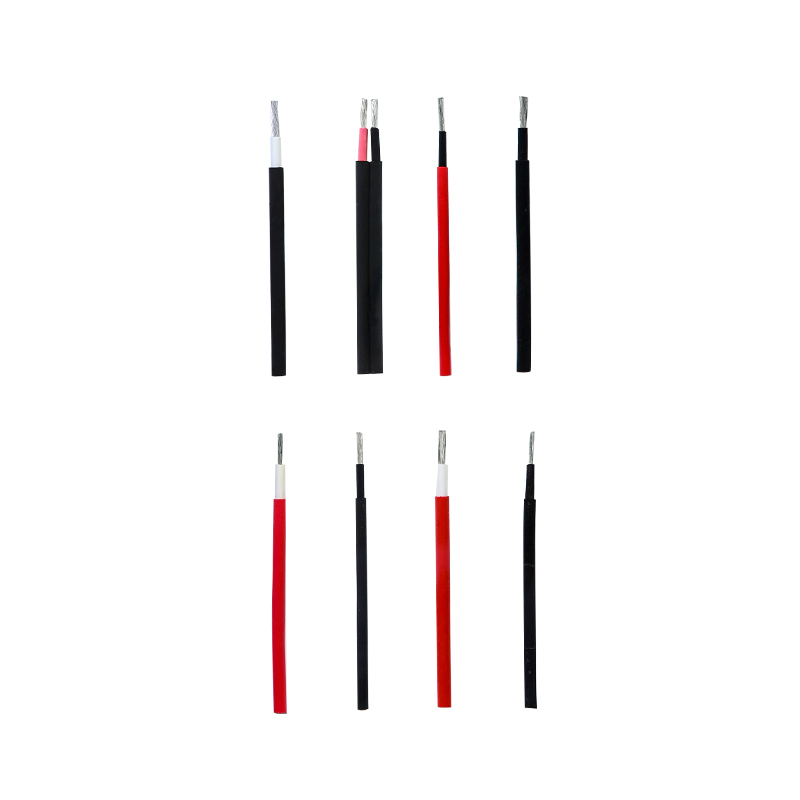
- End-to-end technical support. Support that extends from cable sizing software to on-site jointing supervision reduces commissioning failures. And when the project is located in a region where pest-resistant cables matter, having the same factory build the high-voltage feeder and the mineral insulated cable for the fire pump saves weeks of coordination.
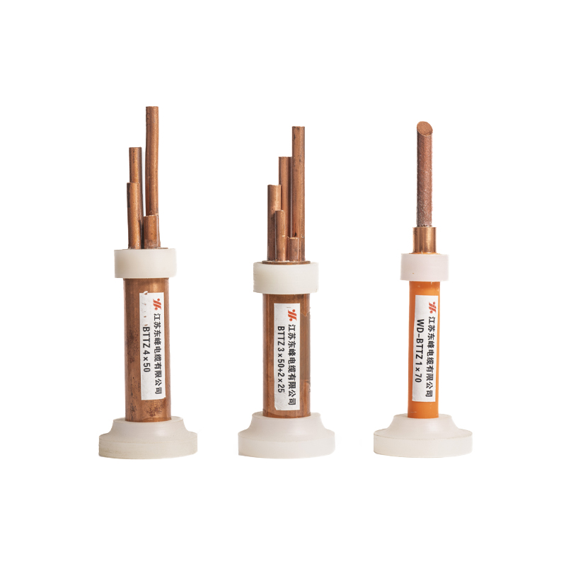
When uptime is measured in hundreds of millions of dollars per hour, the argument for a single-source supply with full traceability writes itself.
PREV: No previous article
NEXT: Battery Cable for Car: Complete Guide to Gauge, Material & Installation
Contact Us
Your email address will not be published. Required field are marked*


Choosing our wires and cables means choosing safety, reliability, and professionalism.

 +86-17826659260
 +86-0510-87203139
 West of Huanzheng Road, Guanlin Town, Yixing City, Wuxi City, Jiangsu Province, China