

 Language
  English
 中文简体
中文简体 Español
 عربى
عربىHome / News / Industry News / Battery Cable for Car: Complete Guide to Gauge, Material & Installation
Industry News

Content
Your car cranks but refuses to start. The dash lights flicker and dim. Before you blame the battery itself, trace the thick wires bolted to its terminals. Those are your battery cables — and they handle more electrical load than any other wire in the vehicle.
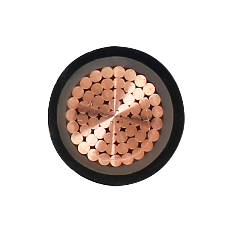
A car battery cable is a heavy-gauge insulated conductor that connects the battery to the starter motor, alternator, chassis ground, and fuse block. The positive cable, always red or marked with a red sleeve, carries current from the battery's positive terminal to the starter solenoid and the main fuse panel. The negative cable, black or bare-braided, grounds the engine block and chassis back to the battery's negative post. Both must carry peak currents of 150 to 300 amps during cold cranking without overheating or dropping excessive voltage.
Manufacturers build automotive battery cables to SAE J-1127 standards. This specification defines three common insulation types: SGT (thick-wall, 0.030-inch jacket for high abrasion resistance), GPT (thin-wall, 0.015-inch for general underhood use), and STX (extra-flexible cross-linked polyethylene rated for higher temperatures). Each uses stranded copper — never solid — because stranded wire survives the constant vibration and flexing inside an engine bay.
Short runs of 3 to 6 feet serve most passenger vehicles. Longer cables, found in trucks, SUVs, and cars with trunk-mounted batteries, require heavier gauges to compensate for voltage loss. The physics is unforgiving: double the cable length and you double the resistance.
AWG stands for American Wire Gauge. The number runs in reverse — smaller digits mean thicker copper. A 2 AWG cable measures 6.54 mm in diameter and handles far more current than a 6 AWG cable at 4.11 mm. This is the single most critical specification when you buy a cable for battery car applications.
Choosing the wrong gauge creates two problems. An undersized cable restricts current flow, causing voltage sag at the starter motor and generating dangerous heat under load. An oversized cable wastes money and adds unnecessary weight, though it guarantees headroom for future upgrades like high-output alternators or auxiliary fuse blocks.
The table below matches common automotive cable gauges to their maximum current ratings and recommended applications. These figures assume pure copper construction and ambient temperatures under 50°C.
| AWG Size | Max Amps (Engine Bay) | Typical Application | Recommended Max Length (12V) |
|---|---|---|---|
| 2/0 AWG | 280A | Diesel trucks, dual-battery systems, high-torque starters | 20 ft |
| 1/0 AWG | 230A | Large SUVs, winch setups, auxiliary power distribution | 16 ft |
| 2 AWG | 175A | Full-size sedans, light trucks, aftermarket audio systems | 12 ft |
| 4 AWG | 130A | Standard passenger cars, stock starter circuits | 8 ft |
| 6 AWG | 90A | Small engines, auxiliary lighting, short ground straps | 5 ft |
| 8 AWG | 60A | Alternator charge wires, fuse-block feeders | 3 ft |
Cold-cranking amps (CCA) draw far exceeds these continuous ratings. A 4 AWG cable rated for 130A continuous routinely handles 250A surges for 10 to 15 seconds during engine starts. The key is duration — short bursts generate less cumulative heat, allowing smaller cables to survive brief overloads.
Walk into any auto parts store and you will find battery cables at two very different price points. The cheaper option is almost certainly copper-clad aluminum. It looks like copper on the outside but uses an aluminum core. The price gap is real — CCA cables typically cost 40 to 60 percent less than pure copper equivalents. The performance gap is equally real.
Pure oxygen-free copper (OFC) carries a resistivity of 1.68 microhm-centimeters at 20°C. CCA measures 2.82 microhm-centimeters — roughly 68 percent higher resistance per foot. That means a 4 AWG CCA cable behaves more like a 6 AWG copper cable under load. Every amp flowing through it generates more heat, and more voltage disappears before reaching the starter.
| Property | Pure Copper (OFC) | Copper-Clad Aluminum (CCA) |
|---|---|---|
| Resistivity at 20°C | 1.68 microhm-cm | 2.82 microhm-cm |
| Conductivity (IACS) | 100% | 60-65% |
| Weight (per foot, 4 AWG) | 0.13 lb | 0.06 lb |
| Tensile strength | 35,000 psi | 18,000 psi |
| Corrosion resistance (salt spray) | 250+ hours (tinned) | 80-100 hours |
| Typical lifespan | 15-20 years | 5-8 years |
Corrosion is the silent killer of CCA cables. Aluminum forms a brittle oxide layer wherever the copper cladding gets scratched — at terminal crimps, under insulation nicks, near battery acid vapors. This oxide acts as an electrical insulator, raising resistance at the connection point until heat builds to failure levels. Pure copper corrodes too, but copper oxide remains somewhat conductive, and tinned-copper terminals routinely survive over 500 hours of salt spray testing.
There is one legitimate use case for CCA: temporary or low-budget projects where weight matters more than longevity. A racing team that replaces cables every season might accept CCA's shorter lifespan. For a daily driver parked outdoors, the cost savings vanish the first time a corroded CCA cable strands your car on a cold morning. Industrial cable standards — such as those used in EV charging cable rated for 450/750V — specify pure copper conductors for exactly this reason.
Start with your vehicle's factory cable gauge. Open the hood and look for the numbers printed on the insulation jacket — most OEM cables are 4 AWG or 6 AWG for compact cars, 2 AWG for mid-size sedans, and 1/0 AWG or larger for trucks with diesel engines. Never go smaller than the original equipment. Going larger is safe; going smaller is dangerous.
Next, measure the total circuit length. Include the full path from the battery positive terminal to the starter motor and back through the engine block to the negative terminal. A cable that looks 4 feet long in a straight line may actually cover 7 feet of routed path. For trunk-mounted battery setups common in European sports cars and some American muscle builds, the positive cable alone can exceed 15 feet — requiring a gauge increase of two AWG steps to keep voltage drop under the 3 percent threshold.
Factor in your electrical load honestly. A stock sedan with a 1.6-liter engine and no aftermarket accessories draws around 120 to 150 amps during cranking. The same car modified with a 1,000-watt audio amplifier, off-road light bars, and an electric cooling fan upgrade may pull 200 amps continuously with the engine running. Each load adds to the cable's burden.
Match the terminal type to your battery. Top-post batteries use ring terminals with a 3/8-inch or 5/16-inch hole. Side-post batteries require specialized bolt-through connectors. Marine-style terminals with wing nuts suit boats and some off-road vehicles where frequent disconnection is expected. Always select terminals made from tin-plated copper — bare copper blackens quickly underhood, and zinc-plated steel terminals introduce galvanic corrosion when bolted to lead battery posts.
Assembly quality separates a reliable cable from a roadside breakdown. Hydraulic crimpers produce cold-weld connections that achieve over 90 percent of the parent copper's conductivity. Hammer crimpers leave voids. Solder-only connections crack under vibration. The best cables combine a full-circumference hex crimp with adhesive-lined heat-shrink tubing that seals out moisture and acid fumes.
A starter motor rated for 12 volts delivers its full rated torque only when it actually receives 12 volts. At 10.5 volts — a 12.5 percent drop — cranking speed falls by roughly 30 percent. At 9 volts, many starters fail to turn the engine at all. The battery may test perfectly on a bench, but a resistive cable steals that voltage before it reaches the load.
The voltage drop formula for a DC circuit is straightforward: V_drop equals 2 times the one-way cable length in feet times the current in amps times the resistivity of copper (10.4 ohm-circular mils per foot), all divided by the cable's cross-sectional area in circular mils. In practice, you can use this simpler rule: for every 10 feet of 4 AWG copper cable carrying 150 amps, expect a drop of approximately 0.38 volts in a 12V system. Double the current or double the length, and the drop doubles.
| Cable Gauge | Drop at 5 ft (150A) | Drop at 10 ft (150A) | Drop at 15 ft (150A) | Meets 3% Limit? |
|---|---|---|---|---|
| 2 AWG | 0.21V | 0.42V | 0.63V | Yes, up to 10 ft |
| 4 AWG | 0.33V | 0.67V | 1.00V | Yes, up to 5 ft only |
| 6 AWG | 0.53V | 1.06V | 1.59V | No — exceeds limit at all lengths |
A 3 percent drop threshold — 0.36 volts in a 12V system — is the industry-standard target for starter circuits. Audio system installers often tighten this to 1 percent because amplifier output power varies with the square of supply voltage. A 3 percent voltage drop at the battery translates to roughly a 6 percent drop in usable amplifier wattage at the speaker terminals.
Installing a new battery cable for your car is a straightforward afternoon project. The consequences of doing it wrong, however, include melted wiring harnesses, electrical fires, and fried alternator diodes. Follow these steps in order.
Industrial cable installations, including those for specialized applications like mineral-insulated fireproof cables and submersible pump wiring, follow similar crimping and sealing principles, proving that consistent termination technique matters across every voltage class.
Good cables fail early because of small installation errors that compound over months of heat cycling and vibration. Each of these mistakes has stranded drivers. Each is avoidable with five extra minutes of care.
Your email address will not be published. Required field are marked*

Choosing our wires and cables means choosing safety, reliability, and professionalism.


 +86-17826659260
 +86-0510-87203139
 West of Huanzheng Road, Guanlin Town, Yixing City, Wuxi City, Jiangsu Province, China