

 Language
  English
 中文简体
中文简体 Español
 عربى
عربىIndustry News

Industry News
MV-90 vs MV-105 Cable: Ampacity, Insulation & Cost Comparison
2026-07-08Content
- 1 What Are MV-90 and MV-105 Cables?
- 2 Key Difference #1: Rated Temperature & Ampacity
- 3 Key Difference #2: Insulation Material (XLPE vs EPR)
- 4 Cost Comparison: Initial Price vs Lifecycle Cost
- 5 Application Decision Matrix: When to Use Which?
- 6 Installation & Termination Considerations
- 7 Standards Compliance: ICEA S-93-639 & NEMA WC 74
What Are MV-90 and MV-105 Cables?
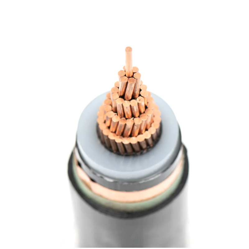
A 4/0 AWG MV-105 cable carries roughly 15% more current than an identical MV-90. That single fact drives thousands of engineering decisions each year. Both are medium-voltage power cables defined under the ICEA S-93-639 / NEMA WC 74 family, with a voltage range from 5 kV through 35 kV. The number in the type suffix tells the story: MV-90 is rated for a maximum continuous conductor temperature of 90 °C, while MV-105 operates at 105 °C. That 15-degree difference has direct consequences for ampacity, insulation chemistry, and total installed cost.
| Parameter | MV-90 | MV-105 |
|---|---|---|
| Max. continuous conductor temp. | 90 °C | 105 °C |
| Voltage class | 5–35 kV | 5–35 kV |
| Common insulation | XLPE (cross-linked polyethylene) | EPR (ethylene propylene rubber), some XLPE compounds |
| Applicable standard | ICEA S-93-639 / NEMA WC 74 | ICEA S-93-639 / NEMA WC 74 |
Both types serve as primary feeders in industrial plants, utility substations, and large commercial buildings. For standard MV-90 applications with XLPE insulation, cable designs typically conform to ICEA S-93-639, as seen in XLPE-insulated power cable for rated voltage 3.6/6kV–26/35kV.
Key Difference #1: Rated Temperature & Ampacity
The 15 °C higher rating of MV-105 is not just a paper number. It translates into a 12–15% increase in continuous current-carrying capacity under the same installation conditions. When a retrofit project cannot enlarge conduit or vaults, that extra headroom often makes MV-105 the only viable option.
The table below shows typical ampacity values for three common conductor sizes, based on copper conductors, 15 kV, 100% insulation level, single circuit, and standard burial/air conditions per ICEA P-53-624.
| Conductor | MV-90 – Underground (20 °C earth) | MV-105 – Underground (20 °C earth) | MV-90 – Air (40 °C) | MV-105 – Air (40 °C) |
|---|---|---|---|---|
| 4/0 AWG | 260 | 299 | 340 | 391 |
| 250 kcmil | 290 | 334 | 376 | 432 |
| 500 kcmil | 380 | 437 | 490 | 564 |
These numbers explain why an engineer might downsize the conductor when switching from MV-90 to MV-105. A 250 kcmil MV-90 circuit, for example, can often be replaced by a 4/0 AWG MV-105 circuit in buried applications, trimming copper weight, conduit diameter, and pulling force. The thermal margin also reduces the risk of hot-spot failures in areas with high soil thermal resistivity or where cable layers are stacked.
Key Difference #2: Insulation Material (XLPE vs EPR)
The temperature rating influences, and is influenced by, the insulation chemistry. Most MV-90 cables are built with XLPE, a thermoset material prized for low dielectric losses and excellent moisture resistance. To reach 105 °C continuously, manufacturers typically switch to EPR, which retains flexibility and thermal stability at elevated temperatures, albeit with a slightly higher dielectric loss factor.
| Property | XLPE (typical MV-90) | EPR (typical MV-105) |
|---|---|---|
| Max. operating temperature | 90 °C | 105 °C |
| Dielectric constant (approx.) | 2.3 | 2.8–3.2 |
| Dissipation factor (tan delta) | 0.001 | 0.005 |
| Flexibility at cold temperature | Good | Excellent |
| Moisture resistance | Excellent | Good |
| Thermal aging resistance | Good up to 130 °C overload | Very good up to 140 °C overload |
EPR’s higher dielectric losses are negligible for most MV feeders, but they start to matter in very long cable runs (over 5 km) where capacitive charging current becomes significant. For outdoor or frequently handled circuits, EPR’s superior flexibility and resistance to water treeing often tip the balance toward MV-105, even when the extra ampacity is not strictly required.
Cost Comparison: Initial Price vs Lifecycle Cost
At the purchase-order level, MV-105 cable typically costs 15–25% more than an equivalent MV-90. The gap widens when aluminum conductors are compared, because EPR insulation and higher-temperature jacketing add a fixed per-foot premium that does not scale down with the metal price. Yet limiting the analysis to initial materials spends misses the larger picture.
A common lifecycle calculation uses the higher ampacity of MV-105 to reduce conductor size. Suppose a feeder requires 290 A in underground duct. An MV-90 solution might select 250 kcmil copper, while an MV-105 solution could use 4/0 AWG copper. The smaller conductor saves copper weight, conduit fill, and cable support hardware.
| Parameter | MV-90 – 250 kcmil Cu | MV-105 – 4/0 AWG Cu |
|---|---|---|
| Cable material cost (approx.) | 100% baseline | 88–92% |
| Conduit size (trade) | 3 inch | 2-1/2 inch |
| Pulling tension reduction | — | ~18% lower |
| Termination labor (105 °C connectors) | Standard | Small premium |
| Net installed cost (material + labor) | Baseline | 5–10% lower |
When conduit and civil work are expensive, the ability to downsize can offset the higher unit price of MV-105 and yield a lower total installed cost. For projects in high-ambient environments, specialty cable solutions may offer further thermal margin, but for most 5–35 kV feeders, the MV-90 vs. MV-105 decision hinges on this exact trade-off.
Application Decision Matrix: When to Use Which?
No single rule works for every project. The choice turns on ambient temperature, load profile, physical space, and total cost of ownership. The matrix below captures the most frequent engineering scenarios.
| Application | Recommended type | Rationale |
|---|---|---|
| Industrial furnace area (ambient > 45 °C) | MV-105 | 105 °C rating prevents derating below required ampacity |
| Data center main feeder (continuous high load) | MV-105 | Extra 15% ampacity reduces need for parallel runs, saving space |
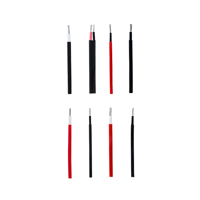
| Photovoltaic array MV AC collection | MV-105 | Outdoor exposure, high daily temperature swings; often pairs with photovoltaic cable on DC side |
| Commercial building riser (normal ambient) | MV-90 | Standard conditions, ample ventilation; cost efficiency wins |
| Retrofit – existing conduit cannot be enlarged | MV-105 | Higher ampacity permits smaller OD replacement cable |
If the installation requires frequent re-routing or tight bends, MV-105’s EPR-based construction also provides an advantage in flexibility, reducing the risk of insulation damage during pulling.
Installation & Termination Considerations
Choosing the cable is the first step. Field practices often determine whether the thermal rating is fully realized. MV-105 cables demand attention in three areas:
- Bending radius. Typical minimum bending radius for MV-90 is 10 times the overall diameter; for MV-105 it is 12 times. This can affect tray layout and pull-box dimensions.
- Termination temperature rating. MV-105 circuits must use connectors and stress cones rated for 105 °C continuous. Installing standard 90 °C lugs creates a weak link and can accelerate thermal degradation at the joint.
- Conduit fill and jam ratio. When downsizing the conductor to save cost, engineers must still verify that the smaller cable’s outer diameter does not increase the jam ratio beyond recommended limits in existing conduits.
Ignoring these details can narrow the operational margin that the 105 °C rating was supposed to provide.
Standards Compliance: ICEA S-93-639 & NEMA WC 74
Both MV-90 and MV-105 cables are tested to the same base standard, but the severity of certain tests reflects the higher thermal rating. The following table highlights the most consequential differences.
| Test | MV-90 requirement | MV-105 requirement |
|---|---|---|
| AC withstand (5 min, factory) | 2.5 × rated voltage + 2 kV | Same |
| Partial discharge (sensitivity) | 5 pC or less at 1.73 × rated voltage | Same (insulation shielded) |
| Hot set test (elongation under load) | 175% max at 200 °C | 175% max at 250 °C |
| Thermal endurance (long-term aging) | 90 °C rating basis | 105 °C rating basis per Arrhenius model |
| Cold bend | –25 °C | –35 °C (more stringent for EPR) |
Specifying engineers should not assume that a cable marked “MV-105” automatically passes all MV-90 tests at the higher temperature. Verification against the manufacturer’s ICEA qualification report remains essential. For sites that require robust XLPE-based designs with a proven medium-voltage track record, XLPE-insulated power cable for rated voltage 3.6/6kV–26/35kV serves as a reference for the insulation system’s baseline performance.
PREV: PVC vs Silicone Wire: The Ultimate 8-Factor Comparison for Engineers
NEXT: Fire System Cable Guide: FPL, FPLP, FPLR Types & Selection Tips (2026)
Contact Us
Your email address will not be published. Required field are marked*


Choosing our wires and cables means choosing safety, reliability, and professionalism.

 +86-17826659260
 +86-0510-87203139
 West of Huanzheng Road, Guanlin Town, Yixing City, Wuxi City, Jiangsu Province, China