

 Language
  English
 中文简体
中文简体 Español
 عربى
عربىHome / News / Industry News / Medium Voltage Cable Sizing: Ampacity, Voltage Drop, and Short-Circuit Checks
Industry News

Content
Suppose you have a 13.8 kV transformer feeder with a calculated primary current of 84 A. A quick ampacity table might suggest a #3 AWG copper conductor. Yet a typical installation in the field often ends up with 2/0 AWG cable. The reason is that medium voltage cable sizing cannot stop at ampacity.
The correct size must also pass voltage drop limits, survive the available short-circuit current, respect practical minimum conductor sizes, and account for real installation conditions such as soil temperature, duct banks, and parallel circuits. Treat it as a verification loop, not a single lookup step.
Medium voltage cable generally means cables rated above 1 kV and up to 35 kV. Common voltage classes include 3.6/6 kV, 6/10 kV, 8.7/15 kV, 12/20 kV, and 18/30 kV. Sizing an MV cable means selecting the conductor cross section, insulation level, and screen construction that allow the cable to operate safely for its full service life under both steady load and fault conditions.
The major checks are contiguous: continuous current-carrying capacity, voltage drop, short-circuit thermal withstand, and derating by installation conditions. In many industrial projects, the final size is decided by the short-circuit or voltage-drop check rather than by the ampacity check, especially when the feeder is long or the fault level is high.
Before starting any calculation, collect the system data. You need the nominal phase-to-phase voltage, the maximum continuous load current, the maximum short-circuit current at the cable location, and the protection clearing time. Installation details matter too: route length, ambient temperature, soil thermal resistivity, depth of burial, and whether the cable runs in a duct bank, cable tray, or direct burial.
Small input errors create large sizing errors. If you assume a 20°C soil temperature but the actual site runs at 30°C, a marginal cable will operate above its design temperature. If you forget to include parallel feeder heating, the same cable will be derated in a real installation. The extra time spent verifying input data is always worthwhile.
For most distribution applications, an XLPE-insulated cable with copper conductors is the default choice. The insulation provides high electric strength, low dielectric losses, and good thermal performance. A practical reference for medium voltage distribution is the XLPE-insulated power cable series rated from 3.6/6 kV to 26/35 kV.
 XLPEInsulated Power Cable For Rated Voltage 3.6/6kV -26/35kV Suppliers, Company Dongfeng China wholesale XLPEInsulated Power Cable For Rated Voltage 3.6/6kV -26/35kV suppliers and XLPEInsulated Power Cable For Rated V...View Product →
Ampacity is the maximum continuous current the cable can carry without exceeding the temperature rating of its insulation. For XLPE insulation, the maximum continuous conductor temperature is typically 90°C, while the short-circuit emergency temperature can be 250°C for copper conductors. The cable cross section must enable the internally generated heat to transfer outward without overheating the insulation.
Start from a base ampacity table, then multiply by correction factors for ambient temperature, soil thermal resistivity, depth, cable spacing, and grouping. A conductor size that works in a desktop calculation can run hot when installed parallel to other loaded cables. The table below gives representative derating factors for common MV installations:
| Installation condition | Approximate derating factor |
|---|---|
| Direct buried in native soil (base case) | 1.00 |
| Direct buried in wet soil with low thermal resistivity | 1.05 to 1.10 |
| Inside a concrete duct bank | 0.85 to 0.95 |
| Cable tray in free air, several cables in contact | 0.90 to 0.98 |
After applying all correction factors, compare the corrected ampacity with the full-load current. If the value is between two standard conductor sizes, choose the next larger size unless a later check forces an even larger conductor.
Voltage drop becomes the governing criterion when the MV feeder is several kilometers long or when the load is high relative to the cable impedance. The three-phase voltage drop can be approximated as Vdrop = sqrt(3) * I * (R * cos(phi) + X * sin(phi)) * L, where R and X are the effective AC resistance and reactance per unit length, and L is the route length.
For medium voltage circuits, the total voltage drop should generally stay below 5% from the source to the load. Many facilities apply a stricter limit of 3% for the feeder alone to leave margin for transformers and secondary conductors. For a 33 kV, 10 km feeder carrying 250 A, a 95 mm² copper cable may have a voltage drop near 3.5%, while a 120 mm² cable brings it below 3%. In such cases the larger cable is selected not by ampacity but by voltage-drop limit.
On a 33 kV feeder, inductance often dominates over resistance, so adding conductor cross section provides only limited improvement. In that case, a higher voltage level or a differently routed cable may be more effective.
A cable in a medium voltage system must survive the worst-case short-circuit current long enough for the protective device to clear the fault. During the fault, the conductor temperature rises sharply because the heat cannot escape quickly. For XLPE-insulated cables, the permitted short-circuit conductor temperature is often 250°C for copper and 200°C for aluminum, but values from the manufacturer's test data should be used.
The minimum conductor cross section for thermal withstand can be estimated as s = I * sqrt(t) / k, where I is the rms fault current, t is the clearing time in seconds, and k is a constant that depends on conductor material and the assumed initial and final temperatures. A 13.8 kV system with a 20 kA fault cleared in 0.2 s can easily require a larger conductor than the ampacity check. This is why the short-circuit check is not optional.
The upstream relay coordination must also be verified. If the relay clearing time is longer than the cable thermal limit, the cable will be damaged before the breaker opens.
In addition to the technical calculations, code and mechanical requirements often force a minimum conductor size. Many medium voltage feeders use a #2 AWG copper conductor as the practical minimum, even when the ampacity calculation would allow a smaller size. Large lugs, termination kits, and pull-in forces all become impractical with very thin MV cables.
Derating factors for grouped cables and buried installations can lower the base ampacity by 20% or more. The true ampacity is the base value multiplied by all applicable factors. If the final value is still above the load current, the cable is acceptable for continuous loading. But the engineer should also confirm that the cable can connect properly to the switchgear, bus, or transformer terminals.
After all technical checks are satisfied, the economic question remains. A larger conductor reduces I^2*R losses and leaves room for future load growth, but it raises first cost and may complicate installation in tight ducts. On a long feeder, the net present value of energy savings can justify the extra cost. On a short feeder, the larger cable may be unnecessary.
Choosing a widely manufactured cross section reduces lead time and avoids non-standard terminations. Common MV sizes in metric systems include 70, 95, 120, 150, 185, and 240 mm². When reviewing product options, the 6-35 kV XLPE power cable range gives a good overview of rated voltages and construction details for typical distribution circuits.
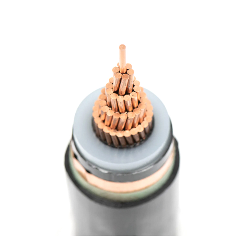 Medium Voltage XLPE Power Cables Manufacturers, FactoryAs China Medium Voltage XLPE Power Cables Manufacturers, Medium Voltage Power Cables Factory, Dongfeng Cable offer Custom 6-35kV Medium V...View Product →
Medium voltage cable sizing is a systematic process: define the system parameters, check ampacity, verify voltage drop, confirm short-circuit withstand, and apply derating plus minimum size rules. Only after those checks pass is it time to weigh cost and availability.
If you are sizing a long feeder or a high-fault-level industrial distribution system, pay special attention to the derating factors and the fault-current calculation. A cable that works at first glance may fail during a fault or at the end of a hot summer day. For more information about insulation temperature ratings and how they affect ampacity, the MV90 vs MV105 cable ampacity and insulation cost comparison is a useful starting point.
Your email address will not be published. Required field are marked*

Choosing our wires and cables means choosing safety, reliability, and professionalism.


 +86-17826659260
 +86-0510-87203139
 West of Huanzheng Road, Guanlin Town, Yixing City, Wuxi City, Jiangsu Province, China